Assembly-izing Tassel
Tasssel: the extra ‘s’ is for “scattering”
Work continues on Corntroller, my sneaky copy of Shane’s sweet brushless motor controller.
I got my Digi-Key order last week and started assembling the board at the Graphics/Visualization/Usability (GVU) Prototyping Lab, the sister lab to the Georgia Tech Invention Studio*, and home to my favorite hot-air reflow station on campus for prototyping.
Now the thing about reflow soldering is that it perfectly captures the sights, sounds, and smells of hell.
What else but hell would make you sit in place, hunched over for hours, as electric fire brings tears to your eyes and solder paste brimstone pierces your nostrils? Bright incandescent lighting, smoldering soldering irons, and in the case of the GVU reflow station, a 50-decibel electric pump all magnify the feeling of burning alive in invidious flames of divine wrath.
But the GVU version of surface mount hell is actually pretty legit. The aforementioned electric pump is hooked up to a precision solenoid valve gas dispenser (controlled by a foot pedal), which in turn feeds pressurized air into a hand-held tube of leaded solder paste. Hit the foot pedal, and a small and carefully controlled bit of gray goop flows out.
The setup basically lets you do manual pick and place assembly. Less efficient for small and medium runs than solder paste stenciling, but way less setup time and a lot more fun†. It’s perfect for prototyping a new board.
Now I ended up shooting video instead of taking too many pictures, so bear with my video screenshots here.
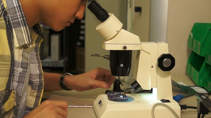
To make life easier, I assemble components under a 10×/30× stereo microscope with tweezers in one hand, solder paste dispenser in the other, and foot on the foot pedal.
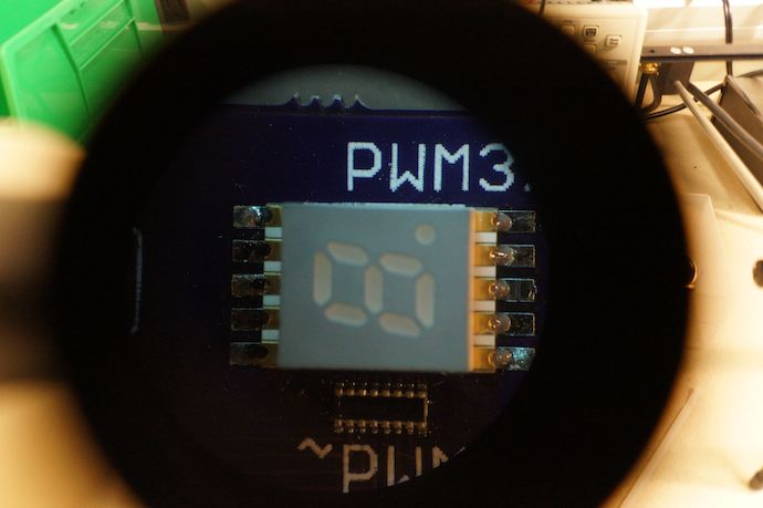
At 10× you can see the particles in the solder paste.
After assembly, I preheat the board over a Zephyrtronics… board preheater.
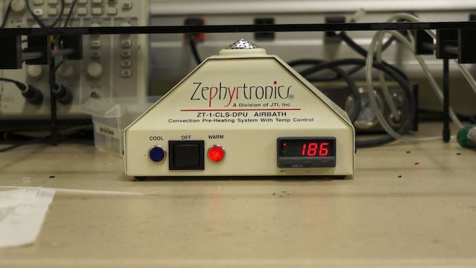
I’m not even making this up. This thing emulates the flat “warm-up” period of the reflow temperature profile you’d use in a full reflow oven. In addition, it has a genius “cool” mode during which it draws air down (instead of blowing hot air up), using ambient air to cool the board (“ramp-down”). No more blowing on the board until your face is red and your tongue is covered with flakes of solder.
It even comes with a sweet PCB jig to hold your board at just the right height above the pre-heater.
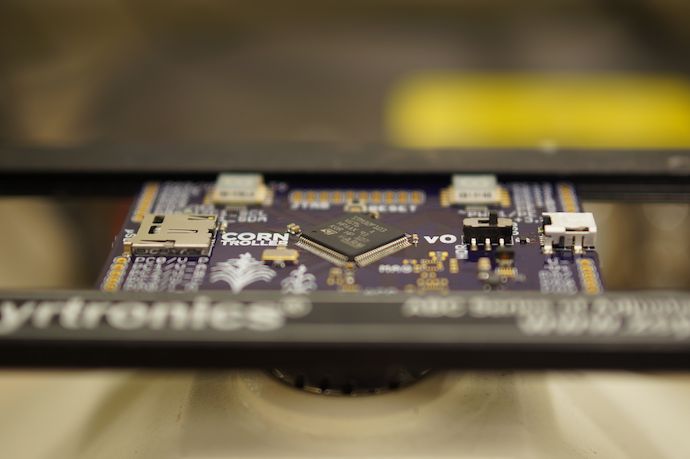
After that, you pretty much just apply heat like a normal person.
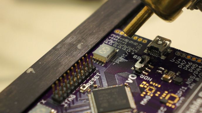
You may notice that in addition to unpopulated inertial sensors, there are also two funny-looking solder bridges.
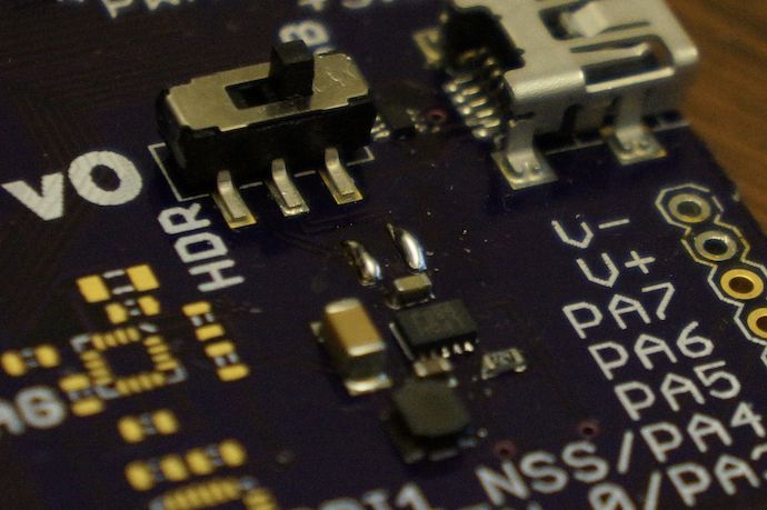
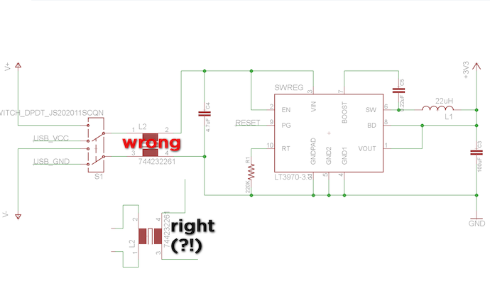
You have ze Germans to blame for that. Had I the European-styled schematic symbols für a common-mode choke ge-used, which had I the wrong orientation for the part ge-using. I think.
In other words, I managed to short my input power leads across a pair of inductors.
Not that that surprises me in the least; I’ve managed to build almost every circuit I’ve ever designed to have a short from power to ground. Heck, this is the probably the highest impedance short I’ve gotten on a first-try board in the past two years.
Actually, maybe the footprint I was using for my Würth-Elektronik common-mode choke just had a mistake in pin assignments. But I like to chalk it up to cultural differences, since it’s 34% more hilarious that way.
At any rate, I ended up skipping the choke completely using solder bridges; I get less noise immunity, but hey, nobody’s perfect and I’m not sure if it would’ve even helped at all.
At this point, it was time to try out the logic power supply. With fingers crossed, I hook up the bench power supply to the V+ and V− power pads and hit the switch.
Nothing.
Turns out when soldering leads to the V− pad while “e-testing” the board, I had broken one of the traces from the pad.
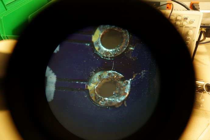
Oops.
I haven’t made a soldering boo-boo this bad in years, but whatever. I briefly considered running a little green wire over the trace‡, but then realized that I tented over all my vias with soldermask§ and couldn’t airwire even if I wanted to.
Instead I just ripped up the soldermask with an X-acto knife under 30× magnification and then solder bridged the shorn copper. Like a boss.
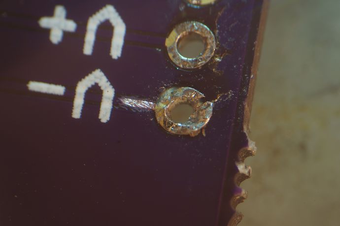
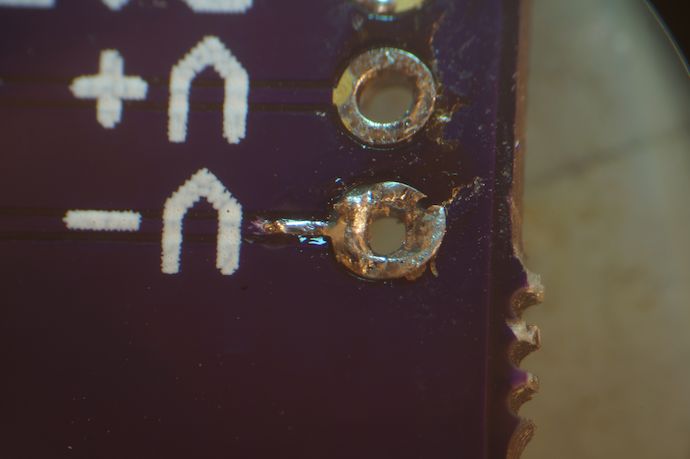
Now I was getting a sweet 3.304V out of my LT3970 circuit from an input of 4V all the way up to 31V, which was as high as the power supply could go. Not really sure why this mattered, since I’ll always be putting 5V into the board, but whatever.
But why the heck am I posting about such minor minutiae as fixing a broken trace when I should be plopping down code like a pro? Well, because performing board bringup¶ on an STM32-based board like this is an (necessary) act of distilled masochism, and I avoid it like a plague even when I’m already working on the board to begin with. I mean, hell, the software you use with the popular GCC/GDB ARM toolchain is called OpenOCD.
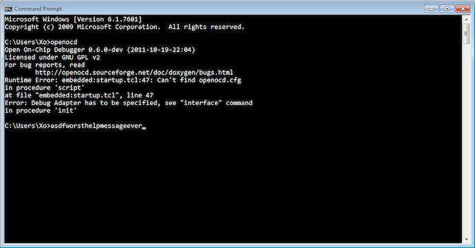
So I plug my board into my Olimex ARM-USB-TINY-H and then pray to Tony Stark to guide my board to a successful JTAG interrogation.
    # See STM Document RM0008
    # Section 29.6.2
    # Low density devices, Rev A
    set _BSTAPID1 0x06412041
    # Medium density devices, Rev A
    set _BSTAPID2 0x06410041
    # Medium density devices, Rev B and Rev Z
    set _BSTAPID3 0x16410041
    # High density devices, Rev A
    set _BSTAPID4 0x06414041
    # Connectivity line devices, Rev A and Rev Z
    set _BSTAPID5 0x06418041
Oops, my STM32F103VG XL-density microcontroller isn’t in there. The comments mention Section 29.6.2 of RM0008, the STM32F1x Family Reference Manual. In section 31.6.2 (dotdotdot) of the newest version of RM0008♠, we see that 0x06430041 is Revision A of XL-density devices.
So I need a more recent version of OpenOCD that has the newer STM32 devices. Crap.
See, I use the default vanilla FTDI drivers for my Olimex, presumably so I can use the Virtual COM Port driver for the broken-out UART the ARM-USB-TINY-H doesn’t have. Yeah, I’m dumb. But OpenOCD doesn’t support those drivers out of the box; licensing issues prevent binary distributors like Freddie Chopin from making available binaries compatible with regular FTDI drivers. Instead most people use libftdi and libusb-win32 for hardware interfacing on Windows.
So I gotta build OpenOCD myself to make it work? God damn it; what is this, Linux?
Let’s just say $ ./configure --prefix=/cygdrive/c/Users/Xo/Desktop/ocd-build/out --enable-maintainer-mode --disable-werror --disable-shared --enable-ft2232_ftd2xx --with-ftd2xx-win32-zipdir=/cygdrive/c/Users/Xo/Desktop/ocd-build/ftd2xx CC="gcc -mno-cygwin"♥
With my new OpenOCD 0.6.0-dev build, I got a fully successful JTAG scan, and the OpenOCD GDB server is now open for business:
C:\Users\Xo>openocd -c "gdb_port 2222" -c "telnet_port 4444" -f "C:/Progra~2/OpenOCD/interface/olimex-arm-usb-tiny-h.cfg" -f "C:/Progra~2/OpenOCD/target/stm32f1x.cfg"
Open On-Chip Debugger 0.6.0-dev (2011-10-19-22:04)
Licensed under GNU GPL v2
For bug reports, read
        http://openocd.sourceforge.net/doc/doxygen/bugs.html
Info : only one transport option; autoselect 'jtag'
1000 kHz
adapter_nsrst_delay: 100
jtag_ntrst_delay: 100
cortex_m3 reset_config sysresetreq
Info : device: 6 "2232H"
Info : deviceID: 364511274
Info : SerialNumber: OLTQ5QMÖA
Info : Description: Olimex OpenOCD JTAG ARM-USB-TINY-H A
Info : max TCK change to: 30000 kHz
Info : clock speed 1000 kHz
Info : JTAG tap: stm32.cpu tap/device found: 0x3ba00477 (mfg: 0x23b, part: 0xba00, ver: 0x3)
Info : JTAG tap: stm32.bs tap/device found: 0x06430041 (mfg: 0x020, part: 0x6430, ver: 0x0)
Info : stm32.cpu: hardware has 6 breakpoints, 4 watchpoints
lol @ C:/Progra~2. Because this thing f—ing breaks if I don’t.

