Bringing up Corntroller
I compensate for my engineering mistakes with bigger engineering mistakes. -Me
Every new board needs an “LED blink” program. It’s basically a Hello, world! for embedded engineers. Thing is, I put two seven-segment LED arrays on Corntroller, my brushless motor controller, so my LED blink program got a little bit fan-çay:
The displays were the first things I wanted to program anyways (USB is next). Among other things, you can display hexadecimal digits on them, which is pretty straightforward from a code perspective:
static struct SevenSegmentDisplay {
public:
	SevenSegmentDisplay(GPIO_TypeDef *gpio, uint8_t offset) :
			gpio(gpio), offset(offset) {
	}

	void showHex(uint8_t x) {
		palClearPort(gpio, 0xF7 << offset);
		palSetPort(gpio, charLUT[x % 16] << offset);
	}

	void setDP(bool dp) {
		palWritePad(gpio, offset + 3, dp);
	}

protected:
	GPIO_TypeDef * const gpio;
	const uint8_t offset;

	static const uint8_t charLUT[16];
} red(GPIOD, 8), green(GPIOE, 0);

const uint8_t SevenSegmentDisplay::charLUT[16] = {
		0x77, 0x14, 0xB3, 0xB6,
		0xD4, 0xE6, 0xE7, 0x34,
		0xF7, 0xF6, 0xF5, 0xC7,
		0x63, 0x97, 0xE3, 0xE1
};
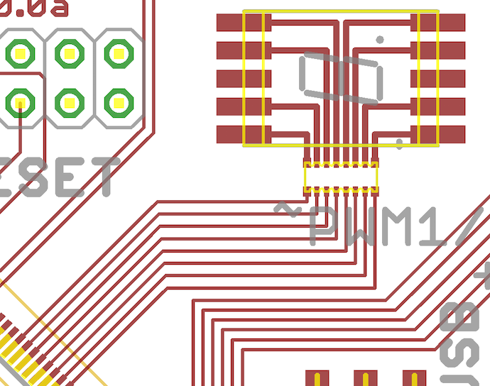
Making that lookup table was the hardest part. Most code is written for “abcdefg” bit order, but my LEDs were bit-swizzled since I rearranged my lines to have a cleaner layout. This just meant I needed different bit patterns:
// - GFABPCDE
// 0 01110111
// 1 00010100
// 2 10110011
// 3 10110110
// 4 11010100
// 5 11100110
// 6 11100111
// 7 00110100
// 8 11110111
// 9 11110110
// A 11110101
// b 11000111
// C 01100011
// d 10010111
// E 11100011
// F 11100001
For a clean layout, it’s totally worth it.

