Corn-Troller: Tassel
Looking around at the hoppin’ electric vehicle scene happening at certain institutions, I realized that pretty soon I’d be playing catch-up to more than just Jamo when it comes stuff-strutting unless I started building something ridiculous, and quickly too.
So in typical son-of-an-accountant behavior, instead of building my own scooter, I decided to go the manic whacky sneaky route and build something to sell to the scooter builders. So now I’m announcing the corniest, trolliest brushless motor controller of them all: Corntroller.

Corntroller is a result of me completely ripping off Shane Colton and Dan Strother to build an extremely feature-bloated brushless motor controller. All of the following will be devoted to driving just a single motor:
- Modular corn-inspired design, stacking a logic board (called Tassel) onto a power board (called HexHusk)
- 10V–45V operation with two switching regulators for logic power (LT3991-5, LT3970-3.3)
- At least 40A of current capacity through IXYS GWM160-0055X1 3-phase MOSFET power modules
- Way too much processing power from a 100-pin STM32F103VG, one of the top parts in the STM32 F1 series of ARM Cortex M3 microcontrollers
- Full voltage and current sensing on everything (motor phases and power bus), so I can implement vector control or sensorlessness
- Compact three-phase N-channel FET driving through dedicated gate driver IC (A4935)
- Motor hall sensor inputs to microcontroller capture timer
- microSD card slot interfaced through SDIO (not MMC over SPI) for datalogging
- Full speed USB interface… just because
- Two 7-segment LED displays… also just because
- Full 9-degrees-of-measure IMU (accelerometer, gyroscope, magnetometer) with the some of the best dumb* MEMS sensors (BMA180, IMU3000, HMC5883L) available… just $@#%ing because
I’m only half-joking about that last one; I designed Tassel, the logic board on Corntroller, as a replacement for my (yet to be written up) Maizure Cortex M3/MEMS sensors board. Maizure has served as my general dev board, and its successor is so full featured and has such overspec’d components because of that. But, I can choose to not populate components for unused features. So when Tassel is used as a part of Corntroller, it will not have its 3-axis MEMS sensor footprints populated†.
By the way, I started naming my projects after corn. Just—you guessed it—because.

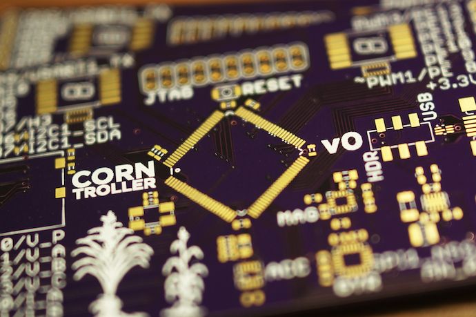
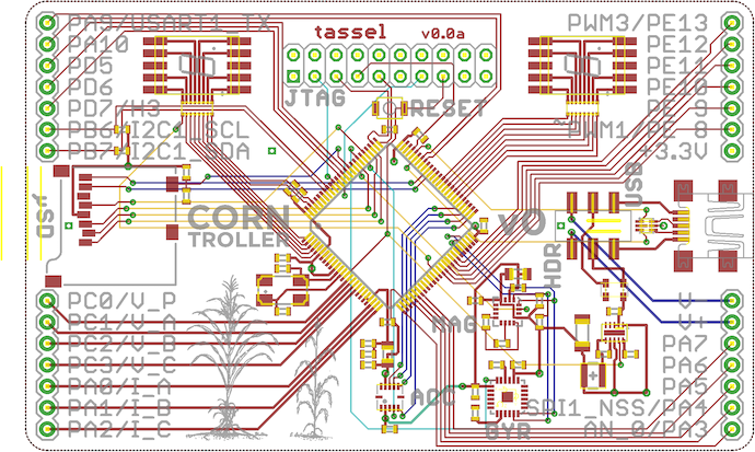
Tassel was laid out with only surface mount components (preferring 0603‡ chip resistors and capacitors), all on the top side. Layout was actually fairly straightforward, since a lot of the work required just routing directly from STM32 pins to headers (which I could reassign anyways).
The hard part was figuring out which peripherals I could route out of the STM32. The original plan was to use a 48-pin device; this grew to 64-pin and then 100-pin as I realized that all the “good” peripherals I wanted in the STM32 were actually sharing the same pins.
For example, USART1 and TIM1 (with its useful three-phase complemented PWM with software deadtime insertion) shared the same pins. I had to spend a solid week assigning pins to their functionalities, restarting all over each time I had to up the pin count and move to a bigger device. Through all of this I also had to make sure to fan everything out properly so wires route cleanly from μC pin to headers and devices.
That’s really how I ended up with 7-segment displays; switching to 100 pins meant I had a lot of I/O pins left over that I didn’t want to go to waste. With the decimal point, each Kingbright 0.2″ display fills up 8 pins: perfect for half a GPIO port, and thus nice to control in software.
Plus, 7-segment displays and resistor arrays are way easier to solder than individual 0805 LEDs and 0603 resistors.
So I ended up with a long list of nets to route well before even starting a schematic in EAGLE (see appendix)!

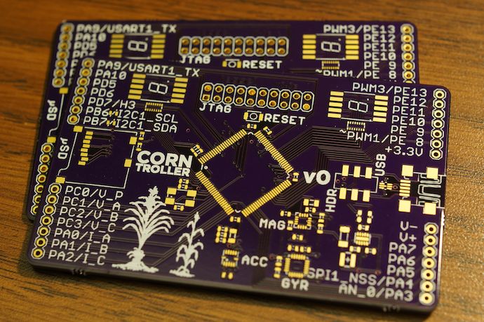
Since Maizure had a bit of problems with noise and stability, I made Tassel a four-layer design. This means extra layers of copper on which to route signals, but more importantly to serve as ground planes for surface signals. This isn’t necessarily needed, but it certainly lends me extra noise immunity I figure I’d want on such a densely routed board.
A four-layer design meant I had way fewer choices in PCB fabrication: I went with Dorkbot Portland’s group PCB order, but also considered 4PCB’s/Advanced Circuits’s $66 each service and BatchPCB’s 4-layer group order. For me, DorkbotPDX just turned out to be the best bang for the buck.

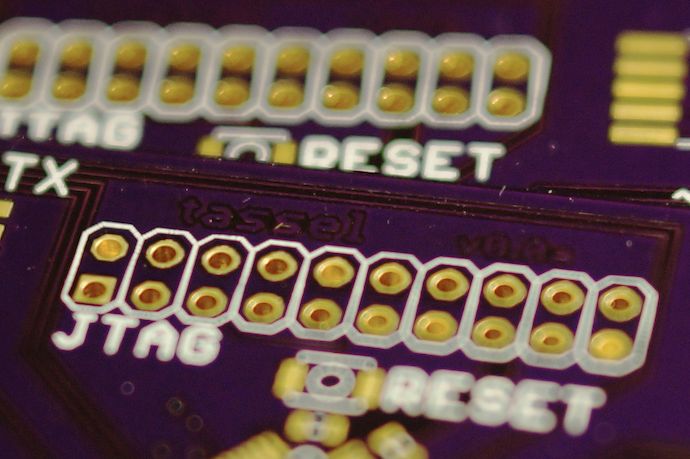
Why do I just have photos of unpopulated boards? Because (a) they’re pretty and (b) I sent these out before I finished designing the power stage, in an attempt to pipeline the prototyping process. I wanted to send these out, complete HexHusk, order parts for both from Digi-Key, and have the components before Tassel’s boards arrived. That didn’t happen… the Digi-Key order is just now in the mail. Guess I failed at pipelining.
Design files for everything and a HexHusk post are coming. I promise.
Appendix Partial pin assignments:
Outputs
=======
# Q1
15 PC0 V_P
16 PC1 V_A
17 PC2 V_B
18 PC3 V_C
23 PA0 I_A
24 PA1 I_B
25 PA2 I_P

# Q2
26 PA3 AN_0
29 PA4 SPI1_NSS
30 PA5 SPI1_SCK
31 PA6 SPI1_MISO
32 PA7 SPI1_MOSI
- V+
- V-

- 3.3V
39 PE8 PWM1~ # remap
40 PE9 PWM1 # remap
41 PE10 PWM2~ # remap
42 PE11 PWM2 # remap
43 PE12 PWM3~ # remap
44 PE13 PWM3 # remap

# Q3
68 PA9 USART1_TX
69 PA10 USART1_RX
# Q4
86 PD5 H1 # 5V
87 PD6 H2 # 5V
88 PD7 H3 # 5V
92 PB6 I2C1_SCL
93 PB7 I2C1_SDA

JTAG
====
- 3.3V
PB4 JTRST
PA15 JTDI
PA13 JTMS
PA14 JTCK
PB3 JTDO
NRST RESET
- V-

USB
===
PA11 USB_D-
PA12 USB_D+
- V+
- V-

SDIO
====
PC8 SDIO_D0
PC9 SDIO_D1
PC10 SDIO_D2
PC11 SDIO_D3
PC12 SDIO_CK
PD2 SDIO_CMD

MEMS
====
PB10 I2C2_SCL
PB11 I2C2_SDA
PB12 SPI2_NSS
PB13 SPI2_SCK
PB14 SPI2_MISO
PB15 SPI2_MOSI