BabyCorntrolling
So I totally ditched Corntroller for its hot redesigned (square!) little sibling, BabyCorntroller.
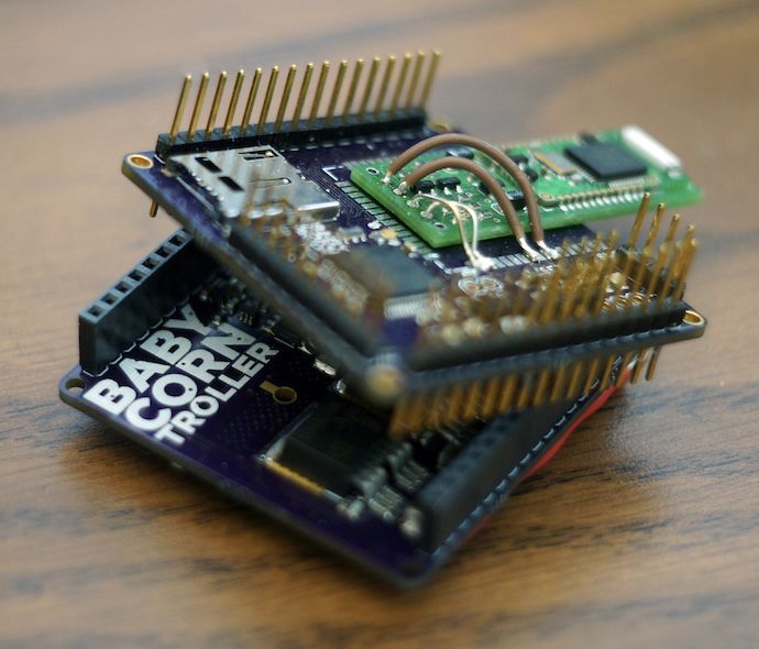
The control (corntrol?) logic board is called MiniCob*. I shrunk down Corntroller’s Tassel from credit card size (3.4″ × 2.1″) to just 1.95″ × 1.95″, while adding a wireless radio, doubling the number of power stages and analog frontends (so I can control two motors), and still keeping the micro-SD card slot. Oh, and going from a four-layer to two-layer layout yet keeping all components on one side.
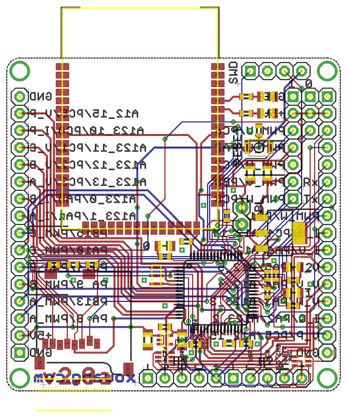
To perform this miniaturization magic, I switched from the 100-pin STM32F103VG to a 64-pin STM32F205RC, which has more flexible pin assignments (every GPIO pin can be muxed to a variety of peripheral functions), supports bootloading on IO interfaces other than USART1, and is faster/has more SRAM for the same cost. Plus, it’s 100% pin-/code-compatible with STM32F4s which run even faster and have FPUs.
I actually managed to use every single pin on the STM32. Wow.
But why 1.95″ square? Well, so I can put the boards through dirt cheap Shenzhen-direct PCB services, in case I want to make like, ten of these.
Meanwhile, the power stage/analog frontend board (HexHusk -> TinyHusk) got a makeover as well. Though Corntroller is a blatant and outright intentional (and very poorly done) clone of 3ph Duo, BabyCorntroller is merely a blatant and accidental clone of Flying Flux. Shane and I had both started our boards before we realized we both had:
- TI DRV830X 3-phase drivers/buck converters/dual low-side current differential amplifiers. I chose the DRV8302, whose dead-time & over-current are set with resistors rather than with the DRV8301’s SPI interface, because I didn’t have the pins to spare for SPI.
- D2PAK-7 FETs (mine are 60V/3.4mΩ/100nC **Infineon IPB034N06N3**s).
- FETs on both sides of the board, with power rails on opposite sides of the board. Unfortunately, this meant I ended up with motor terminals in the middle of the board.
So of course, Shane & I declared motor control design war on Facebook, and finished our boards in record time. Think hackathons, except with hardware, less sleeping, and a whole week in length.
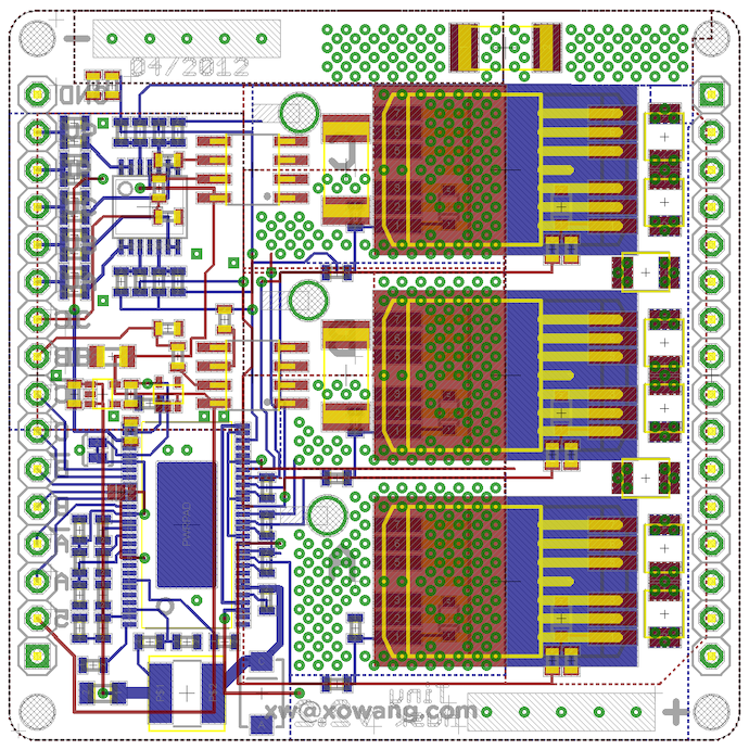
It also goes without saying that I’ve stuffed TinyHusk full of advanced BLDCM/PMSM controller things:
- Six-input PWM so I can leave phases undriven (coasting, six-step commutation, etc). MiniCob is laid out so that its 6-output TIM1/TIM8 PWM modules with deadtime push into these pins.
- Dual-phase current sense (±66A) via ACS714 bidirectional hall-effect current sensors in parallel with 1mΩ jumpers, simultaneously sampled (hells yeah triple ADC) with power bus current sense provided by two low-side 1mΩ resistors in parallel.
- Voltage sense on all three phases, laid out to hit different ADCs so I can simultaneous sampling as well (not very useful, but at least I did it >.>). This is great if I want to do traditional six-step sensorless control.
- Eighteen multi-layer ceramic 1210 50V 10μF caps. These are placed right next to the FETs and serve as the L1 cache of bus capacitance, while two low-ESR/-ESL 680μF aluminum caps chill on the side of the board as my L2.
All of this should allow me to do field-oriented control (sensored or sensorless) with current (torque-mode) control. Regenerative braking, as I understand, comes with the package.
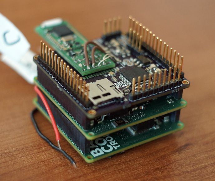
So all this functionality is laid out onto 16 pins on the left side of TinyHusk. So what’s the right-side 16-pin header on MiniCob for? It’s a friggin’ second motor’s worth of pins! It’s rotated 180 degrees so that I can stack two TinyHusks onto one MiniCob, and just rotate one husk board so that they use different headers.
Unfortunately because of school, I didn’t have time to test BabyCorntroller until finals week. So I had less than a week to run them in the Invention Studio before I got shipped out to war an internship in California.
However, before that, I done spant a motor! I implemented six-step sensored commutation with bipolar PWM and ran it up to 32V on a pretty boring BLDC motor.

WOOO IT SPINS. By the way, notice that the motor setup isn’t actually connected to my computer. Wireless trolling opportunities abound. 😉
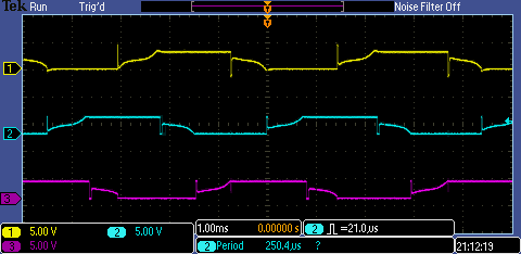
The phase waveforms look hot. Textbook BLDC, Shane says. I was little worried about the reverse voltage spikes when a phase goes undriven—turns out they’re inductive flyback from the field in the phase collapsing then dumping current into the controller, and not some weird PWM glitch.
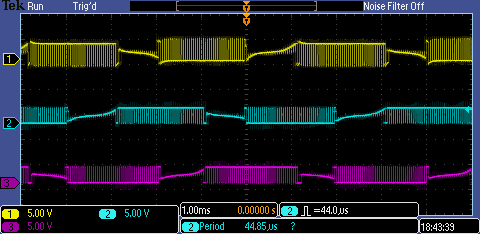
And some more waveforms at a lower duty cycle. Still a nice slope on the undriven phase, though noisier. Now this measured at the motor terminals—my controller’s voltage sampling is buffered and low-pass filtered, so what it sees will be a lot cleaner.
Regen braking works brilliantly, but big current changes (like full stop or full reverse) will spike the bus on my power supply and also cause my controller to get into a trap. I thought this could be the brownout detection kicking in, so I scoped my 5V and 3.3V logic buses with the switching waveform:
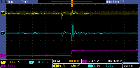
DAT NOISE. The top is 5V, the middle is 3.3V, and the bottom is PWM output going to the driver. Holy crap 3.20V peak-to-peak on my microcontroller power supply. Now granted this is relative to power ground, not logic ground near the microcontroller, so it’s a bit exaggerated, but still. I think this is my fault; there’s just 10μF of logic power capacitance coming out of my 3.3V LDO, plus a few 0.1μF caps the STM32 datasheet asked for. With a few cap upgrades I could make my logic supply a lot more stable.
What’s next? I’ll be implementing rotor angle extrapolation to do leading phase advance, writing a simultaneous sampling triple ADC driver for current control and sensorless six-step, and finding a nice electronics bench near Cupertino.