Delicious Axial Flux Flapjack
WARNING: THIS POST CONTAINS EXTREMELY SHADY ENGINEERING. HOLD NO ILLUSIONS ABOUT THE LEGITIMACY OF THE FIGURES AND METHODS. DO NOT TRY THIS AT HOME.
We’re back to über-technical posts again. Today I’m introducing my current project, a new beetleweight (3lb) combat bot called Flapjack.
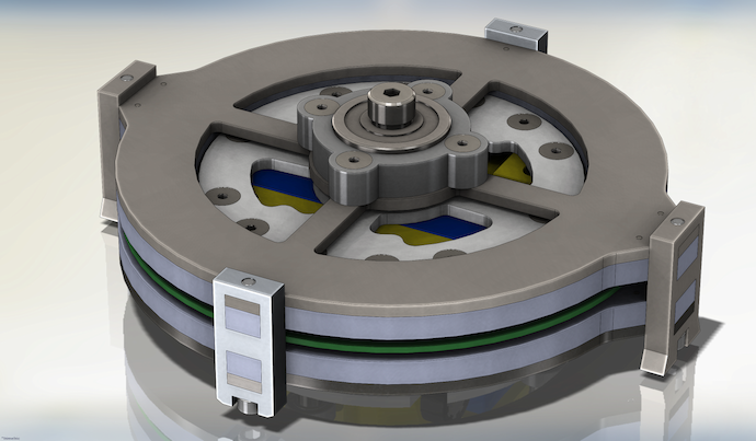
When complete, it will be a super-compact shell spinner where the shell is a unique brushless motor. Here’s the skinny:
- Shell 140 mm in diameter constructed from steel disks separated by aluminum spacers and tool steel teeth
- Custom axial flux 3-phase brushless motor built into the shell, driven by a stator made up of spiral coil traces on printed circuit boards (PCBs)
- Electronics package featuring High Fructose, my custom controller integrating dual brushed direct current (DC) motor drivers, a three-phase brushless motor driver, and gyroscope steering correction
- Four Sanyo-style Pololu gearmotors driving waterjet-cut ultra high molecular weight (UHMW) polyethylene wheels with neoprene tires
- Light, compact chassis made from 3D printed ABS, waterjet-cut polycarbonate and 7075 grade aluminum
- Lithium ion polymer battery providing up to 300 W of power
After watching Dragon*Con, Atlanta Mini Maker Faire, Geek Media Expo, and now Motorama, I’ve gotten just a bit bored of ultra-destructive spinning kinetic energy weapons. Wait, nah; the weapons are always a blast to watch in the arena. What I’m really bored with are the tiny incremental tweaks made to very solid designs that make weapons and armor harder, faster, and bigger, but only in itty bitty steps that aren’t relevant to anyone but other builders.
If I was going to get into the battlebots game, then I wanted to build a game changer. Or at least an attempt at a facsimile of a photo of a game changer. And it’s gotta be a real crowd pleaser too; my previous bot and my first real entry into the hobby, Gyro King, while destructive and nearly bulletproof, was just not that interesting to watch*.
So I figured I could either produce a cool, effective design that doesn’t use rotational kinetic energy as a weapon (very unlikely) or I could try to make a Great Leap Forward in spinner design that makes previous hard hitting bot matches look like church. While I’ve actually achieved neither of those design goals, at least I drew up something where a comically enormous proportion of the weight, power, and space budgets are reserved by a bizarre-looking shell.
Let’s look at a cutaway view of Flapjack.
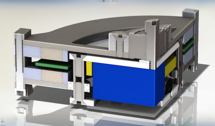
Here you can see two of the 28 3/4″ × 1/2″ × 1/4″ neodymium-iron-boron (NdFeB) magnets arrayed between low carbon 1018 steel plates, creating a 14-pole axial flux rotor. Also, check out the stainless steel standoffs used to support the internal chassis as well as serve as shafts for the weapon’s bearings to ride on. In addition, the shell has a 30mm diameter double-row angular contact bearing that can take loads in axial directions (up and down in this case).
Nearly everything but the fasteners, standoffs, and magnets are designed for 2/3-axis waterjet cutting. The other exceptions include the lithium polymer battery (in blue), which had more or less determined the overall height and diameter of the shell. The stator (in green), a printed circuit board milled out from copper-clad fiberglass laminate, was designed to fit in the airgap of the rotor. Finally, the space inside of the chassis was filled by a 3D printed block (in yellow) holding down the gearmotors, battery, and High Fructose (not pictured).
Now, I was rushing (along with the rest of the Georgia Tech crew) to get Flapjack done in time for Motorama 2013, which was last weekend. And by rush, I mean I really beasted hardcore. High Fructose went from raw parts outta Digi-Key and PCB Unlimited to functional motor controller hooked up to a Hobby King radio set in about four days, and Flapjack went from fresh plates of material from McMaster-Carr and Online Metals to a driving 1290 g bot in about three days. Those timeframes are overlapping, too†.
Documentation and rigor suffered. All I have to justify the designs are barely comprehensible scratches in my notebook. Almost all the hard parts were basically guesstimated. Blogging about Flapjack is my attempt to go back and legitimize some of the horribly back-of-napkinloped numbers I used. Jeff said it best when he pointed out that I basically built a legit-ish bot using ass(bot) techniques.
I’ll start with the glaringly obviously ass part, the permanent magnet coreless axial flux synchronous motor shell and printed spiral wound trace flux linking outer loops, known for short as
PMCAFSMS, P.S. WTFLOL §
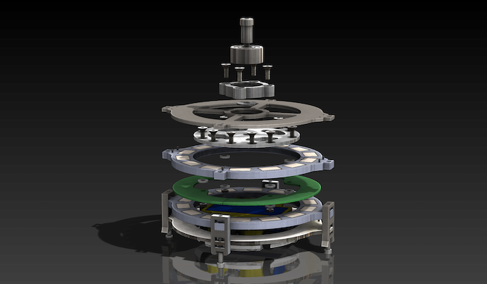
You can see in the cutaway that the rotor, while strictly speaking a shell, is designed more like a ring spinner. So, it really had to respect the outer diameter of the chassis “puck,” which was about 100mm. Given that constraint as well as the weight budget and the magnets available to me, I went with a 14-pole rotor where the lengths of the magnets were lined up tangentially.
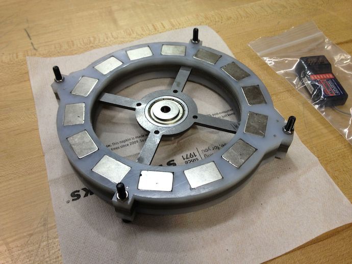
Sadly, I was only able to use 1/8″ of steel for my magnet back iron. According to my FEMM simulation (and real life testing), this means a few flux lines will leak out into the world, sucking up filings off of other bots and otherwise not contributing to torque production.
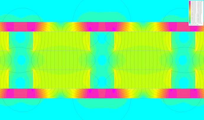
Flux density in the 1/4″ airgap is about 0.8 Tesla, and increasing the back iron thickness to 3/16″ increases this by more than 10%, as does decreasing the airgap to 1/8″. Sadly, the former would make the weapon weigh over 2.5 pounds, while the latter compromises the low-hitting ability of the shell and tolerance to deformation.
Going with a 14-pole, 12-coil design is great for iron-stator motors because it kills cogging torque, but in this coreless motor it just provides a conveniently high Wickelfaktor according to the Bewicklungsrechner‡, which helps to produce more torque with less current (I think). This comes into play because I figured that with my P.S. WTFLOLs, otherwise known as PCB trace windings, I won’t be able to have many turns and thus link a whole lotta flux. Instead, I’ll have to rely on my coil configuration & termination as well as a high airgap flux density to get a reasonable amount of torque. Speaking of windings…
What the Flux Linking Outer Loops? §
Occasionally you have a brainfart and carry it way too far. This whole robot is like that, except worse, because every component was taken the whole nine yards in terms of stupid.
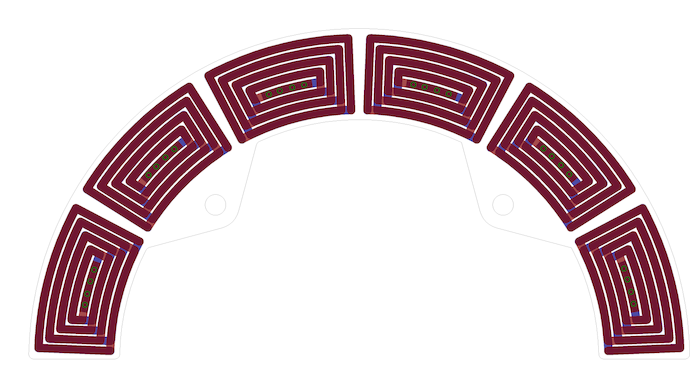
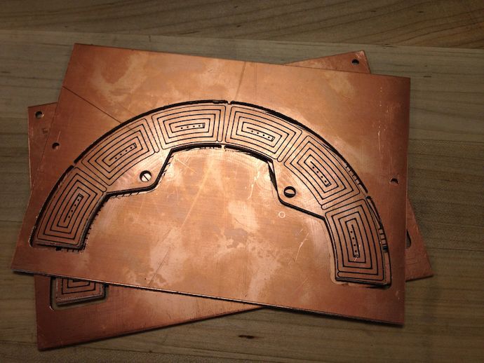
Yeah, that happened. It was formed by a bunch of EAGLE commands generated in an Excel worksheet that I scripted (sigh). I then milled it out on the GVU Prototyping Lab’s LPKF S62 circuit plotter:
Something of note here is that the board is actually 5 oz/ft² copper clad, which is to say that the copper on it is 175 μm thick as opposed to typical copper clad where it’s just 1 oz/ft² or 35 μm thick. The trace width is 1.7 mm, so if I cram 10 A through the coils, that’s about 34 A/mm² of current density, which is incredibly shady.
Also, I measured four of the coils to be 14 milliohms on each four-turn§ side, with about 0.6 μH of inductance. Since the board is double sided (the other side is just the mirrored coil spiralling in reverse), and doubling turns (i.e. one coil on top of another) quadruples inductance, then each full double-sided coil will have 2.4 μH of inductance with 28 mOhm of resistance.
I’ll be connecting four of these in series¶, so in a wye termination, I’ll have 0.226 Ohms of phase-to-phase resistance and 19 μH of inductance (I think; I don’t really know how to combine inductances in this case).
With inductance that low, I’m really thinking about adding external inductors to smooth out the current ripples in the motor, since otherwise Flapjack’s motor looks more like straight strips of copper and less like inductive coils.
Sadly, it’s also a (10 A)² × 0.226 Ohm = 22.6 W loss to just copper heating, and that’s not accounting for eddy current losses from using flat copper oriented the wrong way and not clearing excess copper off of the board. With that efficiency (80% max at 111 W input and 59% at 222W input), Flapjack won’t be driving solar cars any time soon. At least as a coreless motor, I won’t have any stator losses due to magnetic hysteresis, iron eddy currents, etc.
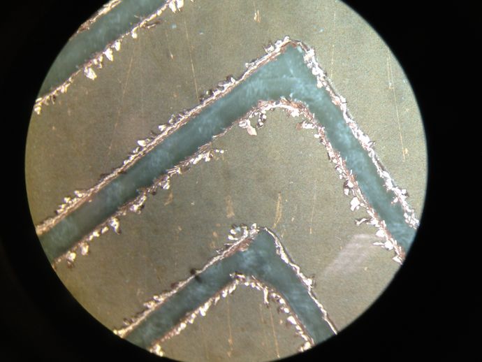
Aside from that, I just feel bad for completely destroying 10 mil and 15.7 mil end mills at the GVU while milling my ridiculous 5oz boards. Notice the difference in quality between that of a fresh end mill (from where I started on the board) and when it got a little less fresh (towards the end of the milling):
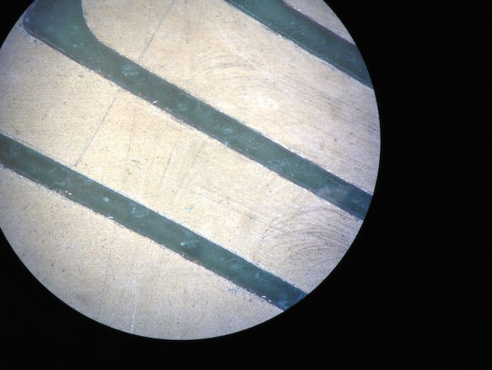
WTFLOL indeed.
Numbers §
I didn’t really feel like setting up a fancier simulation for this thing, since there’s so much fudge to begin with and my controller has even less rigor applied to its numbers♠. Instead I’ll just napkin it up here.
Running 10 A through eight of the twelve eight-turn coils yields, through nibbler (NIBLR):
If you’re on top of this, that’s a Kt of 49.2 millinewton-meter/A, or a Kv of 20.3 radian/second/V, also expressed as 194 RPM/V. Now, since I’m using spiral trace coils that don’t link flux nearly as well as normal circular-section wire wound coils, I’m just going to give my torque constant a fudge factor of 0.7, which makes the Kv 1.43 times higher.
Now we’re talking about a motor putting out 0.34 Nm of torque at 10 A and spinning 3080 RPM at no-load on a 11.1V battery (three-cell lithium). I know from SolidWorks that all the spinny parts of the shell♥ weigh just about 2 lb and has a moment of inertia of 3.32 g-m².
If I can control current (and thus torque) to be constant, then I can get to my no-load speed in:
Also, the weapon kinetic energy would be:
which is comparable to just dropping the whole robot 5 stories.
Current progress §
I actually beasted this thing to 90% completion in time for Motorama, but then blew it up the night before in the hotel (details later). With that deadline over, I’m taking some time to relax and go through some details with more rigor (or at least document the lack of rigor where it exists).
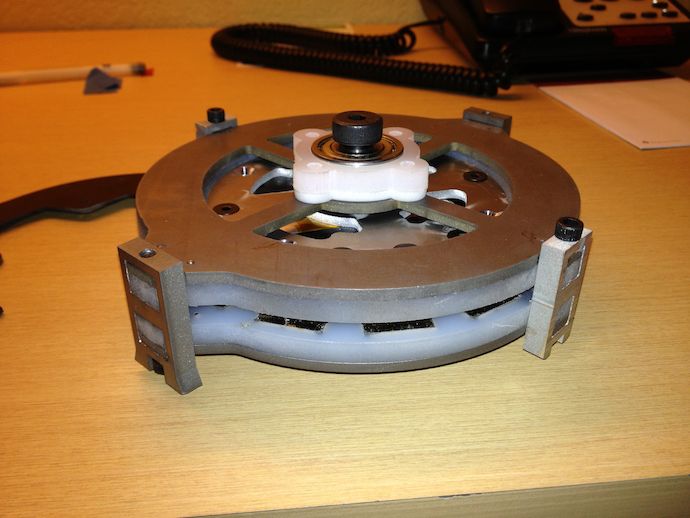
With that said, it drives pretty well, the stators are milled and ready to be wired up, and I just need to make myself a little jig to hold the stator and rotor for testing (the actual chassis isn’t easy or safe to grab onto, for obvious reasons).
Await my next post on the electronics package I whipped up for Flapjack, High Fructose. If you’re really impatient, you can check out High Fructose’s GitHub firmware repository, hfcs (High Fructose corn software).