Sensorless Brushless Can’t Even
Charles wrote a practical and less pointlessly technical post about his SimonK experiments, complete with a 250 lb system prototype. These are my hopefully in-phase science notes.
If you’ve spent any time on hobby avionics and mobile robotics in the last few years, you’ve heard of the “SimonK reflash.” This refers to firmware written by the eponymous Simon Kirby based on the work of Bernhard Konze for the hobby-grade ATmega8-based sensorless controllers for brushless motors.
Quadrotor folks use controllers flashed with SimonK firmware because it does almost no input filtering, nearly directly converting its input, a remote control (R/C) style pulse signals, into its output, a pulse-width modulation (PWM) duty cycle, scaled to to drive a brushless motor. Mobile robotics folks, including those in my combat circles, use SimonK’s effective sensorless startup routines and reversible operation to run traction systems. They speak reverently of the Simon’s amazing powers over aircraft electronic speed controllers (ESCs).
The most bizarre part of this is that the controllers these people are using and hacking are available from the likes of Hong Kong-based HobbyKing for $5.

Five friggin’ dollars.
I live down the street from $4 toast. So the idea that for 20% more than a slice of flame-kissed bran smeared with Fresh Meadows Farm mulberry compote, one can spin three-phase motors sounded serious skeptic alarms in my head.
.jpg)
By the way, a McDouble is $1. Not that it should be, but it is. Bullied farmers, countless suffering animals, and underpaid service workers made it possible.
I bought six units of these (ESCs, not McDoubles) with the intention of figuring out what they’re really worth. Questions I want to answer start with,
- Can this controller spin a motor?
- Can I reconfigure SimonK for this controller so that when reflashed, it still spins a motor?
- Do the cool SimonK features that combat robot folks use work with it?
For brevity (lol.), I’m going to refer to this family of ATmega8A-based sensorless brushless controllers with virtual neutral (explained later) as CCCs: cheap Chinese controllers.
To start, I’m not critically examining CCCs’ or this particular controller’s design and construction. I first want to see it work as rumored. Not to mention that for $5, we know that I’ve bought crappy hardware. It doesn’t do me any good to point out the turd nuggets until later, except as prep work and due diligence.
Can this controller spin a motor? §
Yes.
This on its own is astonishing. The global manufacturing economy has cut out enough middlepeople to offer unit quantity computerized power electronics through retail outfits taking credit card payments in US Dollars, shipped to your door. Take a breath.
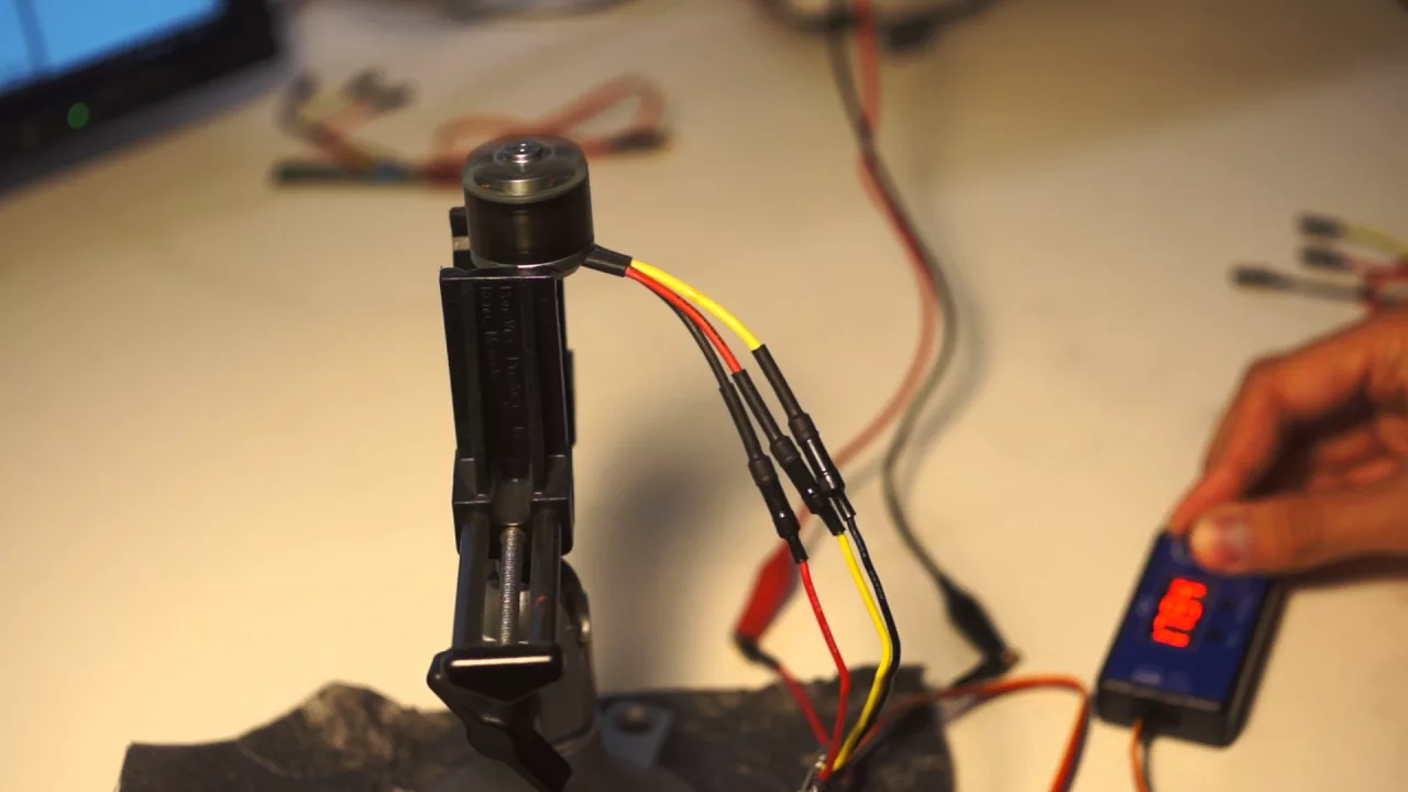
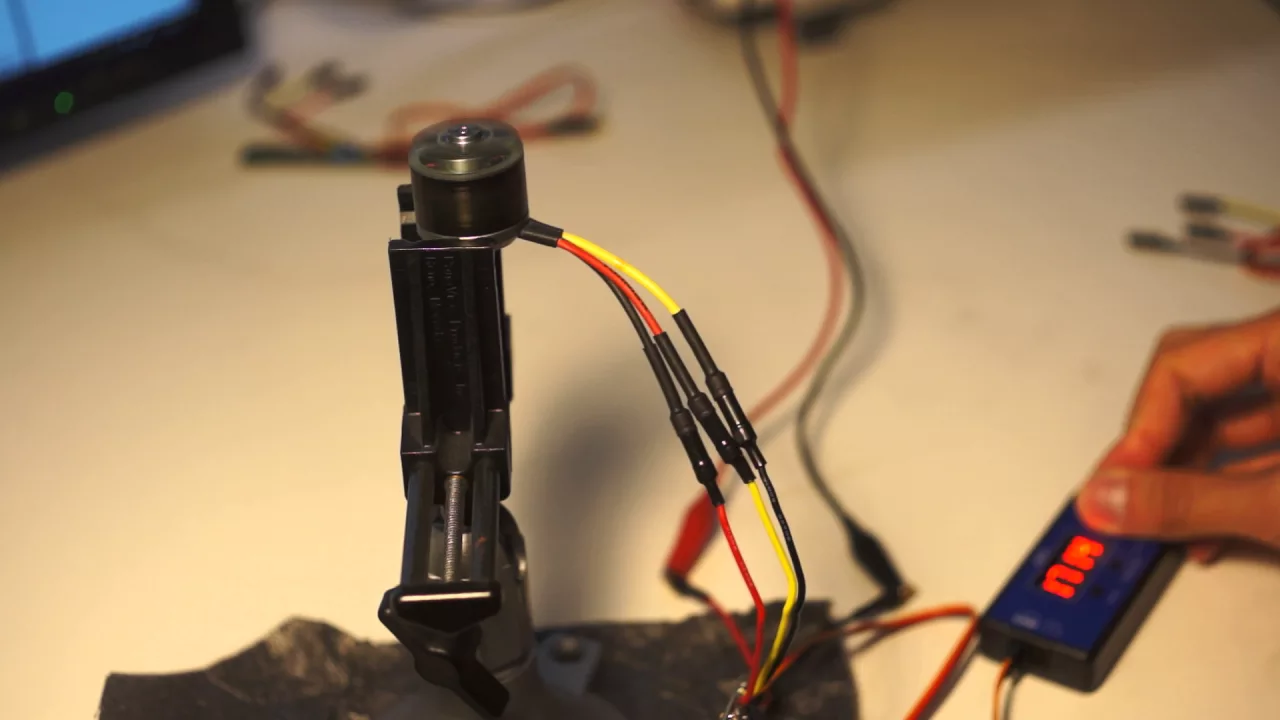
SimonK functional test §
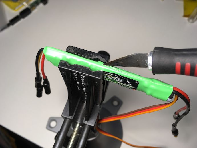
OK, I said I wasn’t gonna delve into the details, but the reflashing requires access to the microcontroller, so I do at least need to take it apart.
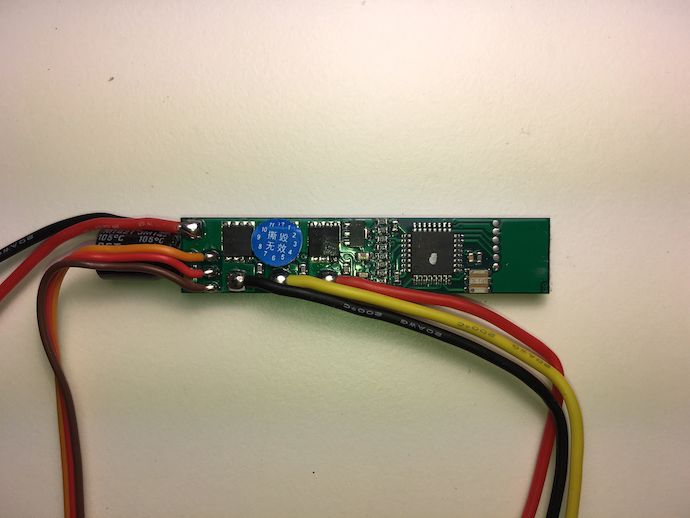
Yup, that’s a motor controller.
Flashing the firmware §
“Reflashing” refers to programming the device-internal flash memory in the Atmel ATmega8A microcontroller that runs the motor controller with different firmware.
Confession: I’ve never actually programmed an AVR (the Atmel 8-bit microcontroller class of which the ATmega8A is a member) over its in-system programming (ISP) interface before. I’ve “uploaded” a few Arduino “sketches,” but that’s sending the code over a serial link to the Arduino’s already-running AVR, which programs the code to itself.
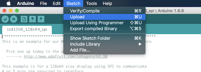
In hobbyist argot, the program the microcontroller is running to do this self-programming is called a bootloader, which confusingly is a definition contrary to the use of the word outside of internal-flash system-on-chip (SoC) devices*.
The alternative is to connect an ISP device that externally drives the programming process. I want to program with an ISP programmer because I don’t know if the ESCs have a bootloader that I could rely on. External programming allows you to recover from mistakes (bootloaders can and do erase themselves) and is robust over different microcontroller models.
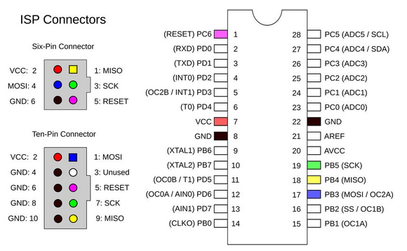
Inexplicably, AVR ISP has two different standard connectors for its physical interface, a 6- and a 10-pin. You could argue that the pinout on the 10-pin insulation-displacement contact (IDC) connector puts a ground wire between every signal-carrying conductor, improving signal integrity, but it’s a several megahertz protocol that doesn’t really need that kind of consideration.
In my pile of crap, I found a Bus Pirate, Sparkfun Edition that has a 10-pin IDC header not for ISP programming and for some reason, a Pololu USB AVR programmer that has a 6-pin header.
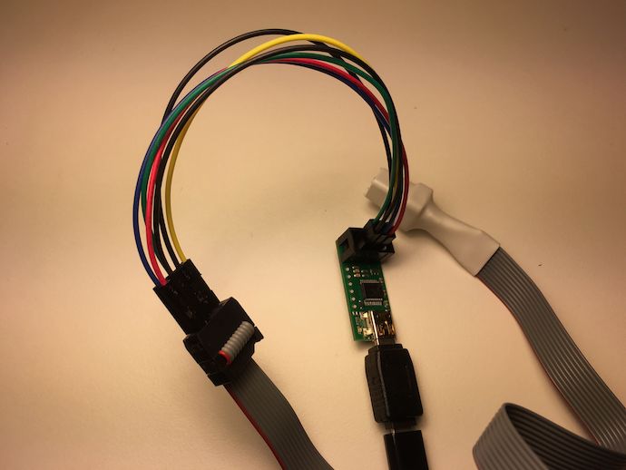
I hacked up an adapter and promptly ordered a programmer with a 10-pin header.
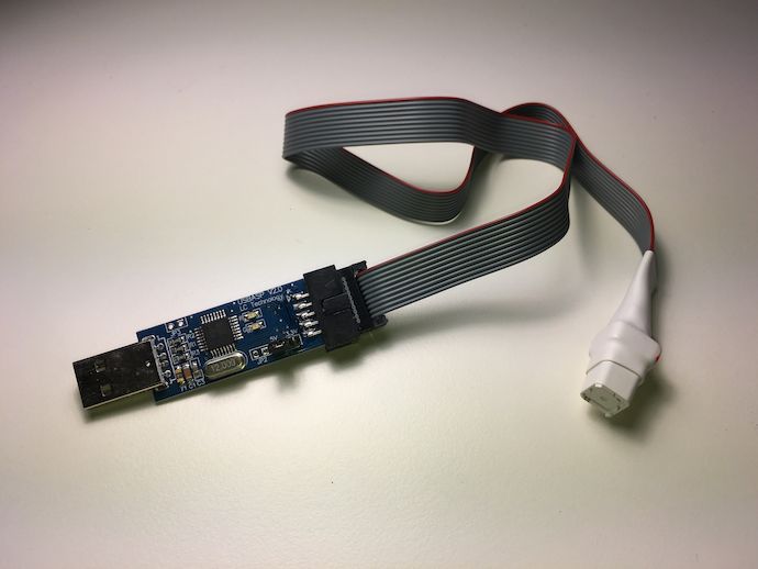
The most notable thing about this setup is what the 10-pin header is attached to. It’s a socket programming fixture for the TQFP32-packaged ATmega8A. It routes the programming signals to spring-loaded claw pins positioned over the correct gull wing leads. This lets you program a chip that’s soldered down, even if its board has no programming header exposed. I suspect it’s the tool used by HobbyKing for production on some its boards that lack test points, although these points are present as a row of solder blobs adjacent to the microcontroller on the 20 A board.
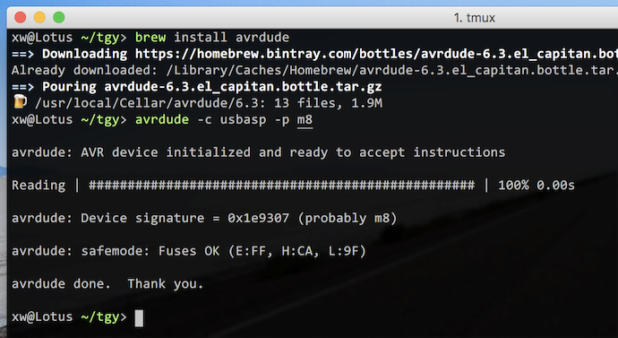
Other than that, it’s a straightforward invocation of AVRDUDE to flash each controller. On OS X, AVRDUDE is available on Homebrew.
Building the code §
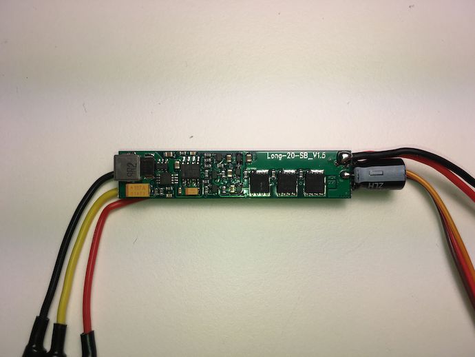
Now the question is how to get and build the SimonK code for this controller. The easiest way to do this is to have bought a controller on this Google spreadsheet to begin with: ESC specs for Simonk / BLHeli FW flash. My controller (product ID 9351000061-0) isn’t on there, so I looked at the closest ones in the HobbyKing Multistar section.
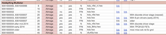
That gives me the choices of kda.hex, kda_nfet.hex, kda_nfet_ni.hex, kda_8khz.hex, and dlu40a.hex, each a board target for which the SimonK code can be configured to build. There’s also a chance that the design is totally different from those entirely, since the form factor did change and thus Charles’s “Law of Chinese Packaging Inertia (‘If the Chinese product looks the same, it probably is the same’)” doesn’t quite apply.
In the Makefile, there’s a suffix rule for .inc to .hex, so I know each of those .hex targets were built from the corresponding .inc (by symlinking ¯\_(ツ)_/¯ the source basename to that of its target…).
Looking at the board, I know it’s all N-channel power transistors (FETs) so kda.hex and kda_8khz.hex are out. dlu40a.inc mentions opto-isolators and has the wrong resistor values (O_POWER and O_GROUND) so its target HEX can be eliminated as well.
That leaves kda_nfet.hex and kda_nfet_ni.hex. Their .inc’s differ only on whether they invert the pulse width input signal. I couldn’t trace any inverting transistor from said input (the orange wire) to the microcontroller so I was leaning 80% towards kda_nfet_ni.hex. Getting that wrong doesn’t blow anything up, but getting the power stage polarity or pinout wrong does, so I double checked the .inc declarations against the board. The resistor divider values were also wrong, but I had a hunch they didn’t matter too much.
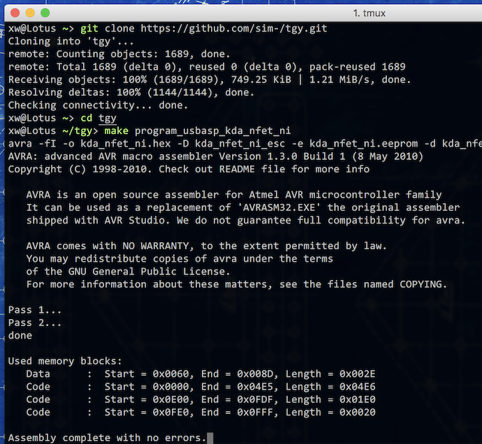
Downloading the code is fairly straightforward, since it’s on GitHub. I also needed to install avra, an AVR assembler.
brew install avra
git clone https://github.com/sim-/tgy.git
cd tgy/
make kda_nfet_ni.hex
avrdude -c usbasp -p m8 -U flash:w:kda_nfet_ni.hex:i
After that, it was just a matter of building the .hex target with make and flashing the file to the controller.

And it worked. First try.
Now, this all seemed “easy” because I yolo’d my controller using an educated guess at a working config. However, you should never take the account of something being easy from an embedded systems engineer at face value, because we’re about as credible on easy things as is an email from Lagos promising rewards for breaking Bernie Madoff out of prison, especially if firmware is involved.

More importantly, you shouldn’t be yolo’ing non-$5 hardware. The remaining 20% outcome of my 80% confidence in kda_nfet_ni.hex was that the controller literally catches fire. There’s a real discovery process to finding—or writing—a board config (the .inc file) appropriate to your controller before you flash it. It’s a combination of tracing connections on its printed circuit board (PCB) for microcontroller pin assignments and analyzing polarities used by the stock firmware with a multimeter or oscilloscope. Charles’s writeup has an example of this and the SimonK README describes the full setup process.
Customizing options §
Since the setup went so smoothly, I jumped directly into configuring SimonK for “robot drive.” These are control paradigms that set controllers used for mobile robot traction operation apart from say, R/C airplane propeller drive.
I deduced what these options mean through a combination of reading the code (it’s 4000 lines of AVR assembler, by the way), guessing “how I’d implement it,” and through empirical testing with a radio/servo tester and an oscilloscope.
Regenerative braking (COMP_PWM) §

With SimonK in its default configuration, the action of the three-phase inverter in the controller is alternating between exciting the in-phase coils (one high-side leg on and one low-side on†) and diode freewheeling (only one high side on). The fraction of the time spent exciting the coils is then the fraction of the bus voltage that is applied to the motor; the motor will accelerate until its induced back-EMF (BEMF) reaches this fraction.
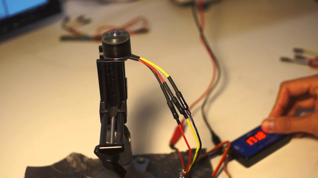
However, neither of those states allows the motor to return energy to the bus, unless its BEMF (which is linear to its speed) exceeds the bus voltage plus the FETs’ body diode forward voltage‡. In the first video above, you can see that reducing the throttle causes the motors to coast and slowly reduce its speed until it matches the applied (fractional) voltage.

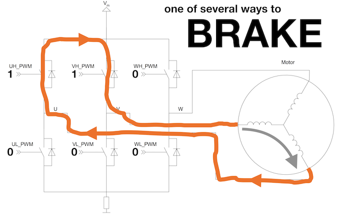
Regenerative braking is a result of using different pulse-width modulation (PWM) schemes that allow the motor to flow current back into the controller’s bus during at least part of the cycle. SimonK’s optional PWM scheme alternates between exciting the in-phase coils (one high-side leg on and one low-side on) and “active” freewheeling (two high-side legs on). The active freewheeling both brakes the motor (applies torque in the opposite direction of motion) and allows the driven phase windings act as a boost converter.

Now you can see that the motor’s speed closely tracks the applied throttle. This is because when the BEMF of the motor exceeds the PWM duty cycle × bus voltage, the motor returns current to the bus. This is the reverse of exciting the motor, so current is allowed to flow in both directions and will want to flow until the motor’s BEMF matches its applied voltage.
This is called COMP_PWM in the code because the phase that switches between high-side conducting and low-side conducting is toggling between its complementary FETs.
This is slightly misleading because other PWM schemes like locked antiphase or space vector modulation (SVM) also use complementary PWM.

An electrical engineer might consider that motor speed changes don’t happen instantaneously, but instead acts analogously to a series RLC (resistor-inductor-capacitor) circuit. The motor speeds up or slows down (increasing and decreasing BEMF) like the charging and discharging of the capacitor (C). The inductance (L) of the phase windings offers “inertia” against current (I) changes. The stiff voltage source is the battery with bus capacitance, and its voltage (V) varies with PWM duty cycle. And to damp the current sloshing in and out of the capacitor/motor speed/induced BEMF is the resistance (R) provided by the motor windings, inverter rDS (on), and to some degree, the bus capacitors’ equivalent series resistance (ESR).
You might also consider that this is very little damping, so regenerative braking results in massive current spikes, and you’d be right. Without some limit to how quickly the PWM duty cycle slews or better yet, feedback control against sensed current, complementary PWM destroys motor controllers.
Reversible operation (RC_PULS_REVERSE) §
SimonK has an option to interpret its throttle input as bidirectional, with commanded speeds in opposite directions mirrored across a neutral point between the extremes of the input range.
Combined with COMP_PWM, this RC_PULS_REVERSE option allows “four-quadrant” (4Q) control of your brushless motor. This means that either forward or reverse torque can be applied to a motor that is spinning forward or in reverse. As you can imagine, this is critical to brushless motors used for mobile robot traction applications, where differential steering like on skid-steer loaders and tanks is the norm. In this drivetrain scheme, torques are commanded in either direction while at any position or velocity.
I’m pretty impressed by the firmware’s ability to maintain rotor tracking during directional changes§.
Neutral braking (MOTOR_BRAKE) §
While it’s a bit hard to tell that the motor is reversing in the RC_PULS_REVERSE video, it’s easier to tell that when the motor is command to zero speed, it’ll coast until it comes to a stop.
SimonK (and even most stock airplane ESC firmwares) provides an option to brake the motor by turning on FETs along one side of the inverter. This short circuits the induced current through the inverter. Due to Lenz’s law, the direction of the induced current creates a torque that brakes the motor. Like when driving the motor, the braking can also be PWM’d so it’s only active for some fraction of time (BRAKE_POWER setting).
The result is quicker stopping when the motor is commanded to neutral or zero speed. This stopping torque would be more significant when multiplied by gearing as in a traction system.
A lot of additional settings cover braking torque and ramping.
Variable timing advance (MOTOR_ADVANCE, TIMING_OFFSET) §
“Six-step” sensorless controllers like CCCs are so named because they approximate three-phase alternating current (AC) output using six steps of PWM’d direct current (DC) output, with each step representing one-sixth or 60° of a rotation. DC drive takes up only two motor phases, leaving the third undriven and monitored for the motor’s BEMF. The transition between each step is called commutation.
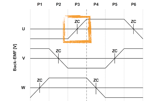
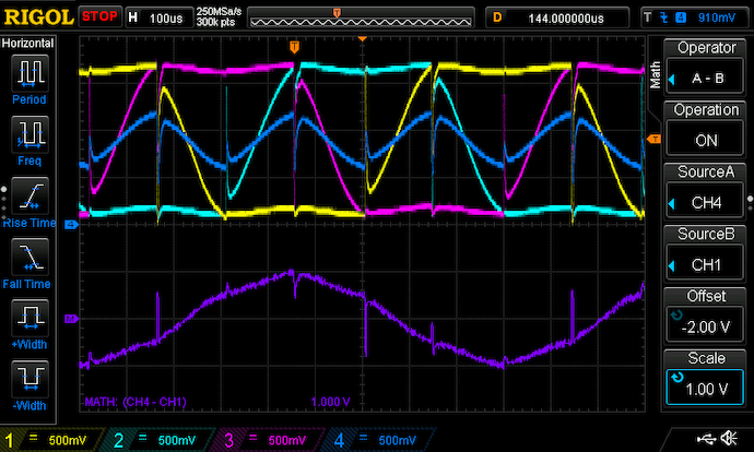
Notice that when a phase is left undriven, the BEMF it shows moves from its previous step’s DC state (+ or −) to its next step’s DC state (− or +). The controller monitors this transition specifically looking for a negative-to-positive or positive-to-negative sign change, or zero-cross, because it occurs at 30° of rotation past the previous commutation.
By the way, the “zero” referred to isn’t the negative bus voltage (i.e. the inverter’s zero), but rather the voltage at the motor’s star—or “neutral”—connection (i.e. the motor’s zero). For simplicity with PWM at 100% duty cycle as shown, the voltage at the motor’s zero is roughly equal to (Vbus+ + Vbus−) ÷ 2, the average of the inverter’s buses. So for these voltage timing diagrams, you should picture it from the motor’s perspective with zero volts floating at half bus voltage.
Assuming the rotor is spinning at constant speed, the zero-cross occurs halfway in time through each step. Given the duration (Tzero-cross in the timing diagram) between the previous commutation and the zero-cross, the firmware extrapolates the time it takes to rotate to the step’s full 60°. It schedules the next commutation for that time, which theoretically is Tzero-cross from when zero-cross happened.
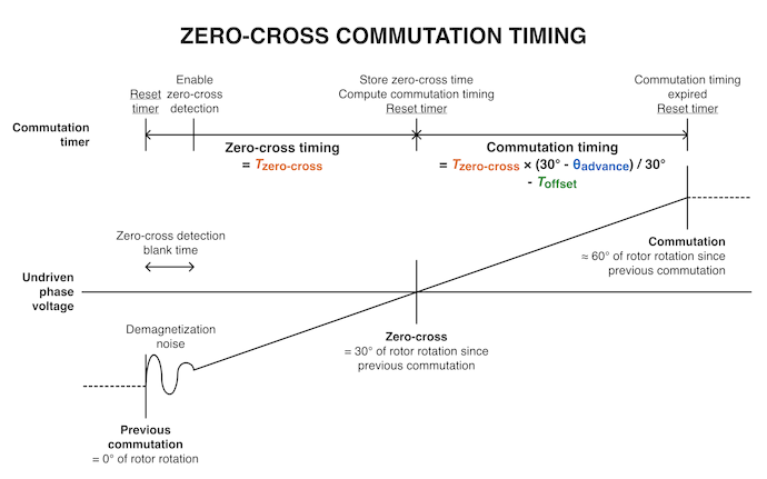
However, “commutation” from the point of view of the motor controller is simply the voltage applied to the motor. It doesn’t reflect the current running through the motor, which can be delayed significantly by the phase windings’ inductance. So like most sensorless firmwares, SimonK provides a timing advance option. It schedules commutation events to occur ahead of reaching the 60° rotation mark, all the way up to advancing to the next step immediately after detecting zero-cross at the 30° rotation mark¶. The MOTOR_ADVANCE option expresses the number of degrees by which to advance (i.e. to subtract from the ideal 60° step duration), corresponding to the θadvance parameter in the timing diagram.
Moreover, there’s yet another option, TIMING_OFFSET, that expresses the microseconds by which to advance the next commutation. As you might imagine, a fixed amount of advance time represents a greater fraction of a cycle as speed increases (and cycle times go down), creating a greater effective phase advance. This setting corresponds to the Toffset parameter in the timing diagram.
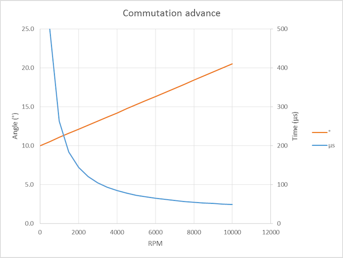
So, this option in effect creates variable timing that commands a more aggressive timing with increasing speed. There’s even a fan-made calculator to compute how much timing advance you get at different speeds. In my videos, I was running 2° of MOTOR_ADVANCE and 37 μs of TIMING_OFFSET that I found to hit a happy local minima for low-throttle current draw.
Other tweaks §
SimonK has a huge number of configuration options, without much organization between board configuration, controller functionality, and user preference customization.
- Input range:
STOP_RC_PULSandFULL_RC_PULSrepresent the range of pulse widths to use as throttle input. WithRC_PULS_REVERSE, they are actually max speeds at opposite polarities, with a zero speed input at their average. SimonK firmware can also be “calibrated” to store these endpoints in non-volatile memory (the AVR’s EEPROM). Also of note are limits for too-short and too-long pulses that should be rejected:MIN_RC_PULSandMAX_RC_PULS. Pulse widths that fall outside of the [STOP_RC_PULS,FULL_RC_PULS] range but fall within [MIN_RC_PULS,MAX_RC_PULS] are clamped to valid power values. For the tests above, I set my limits to [1100 μs, 1900 μs]. - Deadband: with
RC_PULS_REVERSE, the controller needs a region in the center of the input range that represents a “zero speed” command. Due to timing variations in R/C systems (whose transmitters also have non-negligible slop in their control sticks) and even microcontrollers, it’s difficult send a pulse that is guaranteed to be received as a certain width by the ESC. I set myRCP_DEADBANDto be 20 μs on either side of the center of my input range (1500 μs). - PWM frequency: the PWM generation in the SimonK code is done by loading the duration of on and off intervals into a timer and waiting for its overflow interrupt, so the resulting frequency isn’t exact (and probably has some jitter). However, it’s roughly a touch less than
F_CPU/POWER_RANGE. My 16 MHz board with aPOWER_RANGEof 856 was then running at something like 18 kHz, which is corroborated by oscilloscope shots. - Minimum duty cycle: once the motor is running,
MIN_DUTYis the minimum time in each PWM cycle that the inverter is exciting the active phases. This is limited by how quickly the low-side FETs can turn on then off (i.e. apply torque) and by how little average voltage will spin the motor quickly enough to generate a usable BEMF signal. With the aggressive default timing advance of 18° and a default minimum duty cycle of 6.5%, the minimum no-load speed of this ESC/motor combination was unreasonably high. Moreover, for human control it’s kind of unexpected that the effective commanded throttle should jump from 0 to 6.5% at a few percent stick position.
There are more options related to motor start behavior (on its own a broad topic) and I want to explore them in greater depth before offering remarks.
What’s with the assembly code? §
These days it’s pretty rare that a widely used open source project is written in some computer’s assembly language. The code is basically unreadable to even most electrical/software engineers. Writing assembly requires a lot of tedious busy work like register management and call variable passing, so a lot of functionality is hidden behind verbose “boilerplate” code for say, subtracting 24-bit numbers.
On the other hand, given that the code is wholly optimized for a single (very limited) microcontroller running on a narrow family of ESC boards, assembly makes sense. Really, the tiny code space available on the microcontroller and the verbosity of AVR’s RISC instruction set assembly puts a soft limit on how complex the code can get. To me, that’s a blessing. As a result, the complexity of functionality in the firmware is fairly manageable, even if writing and debugging new features might be difficult without a lot of underdamped head-desk interaction.
Next: How does this even work? §
Now that I’ve looked whether the firmware/controller combination works, I wanted to dig into how it works.
The most pressing question for me is, how do CCCs spin motors with such minimal microcontroller hardware? How does it, running SimonK or not, perform all the sensorless motor control tasks like detect BEMF zero-crossing and switch shoot-through unprotected inverters without exploding them?
SCIENCE TO BE CONTINUED.